Gettin' jiggy with it
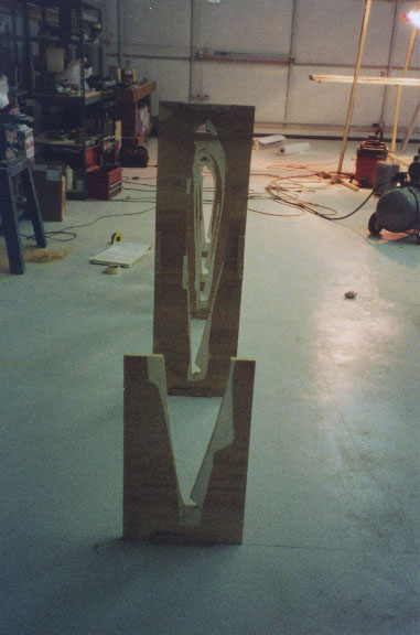
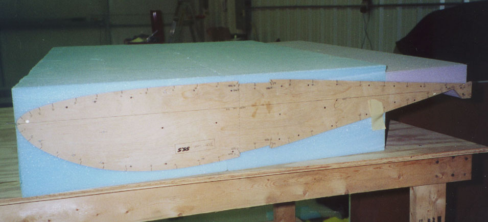
Cut the foam blocks to size and lay templates on them:
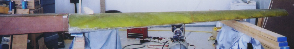
Then hot-wire a perfect core, if I do say so myself:
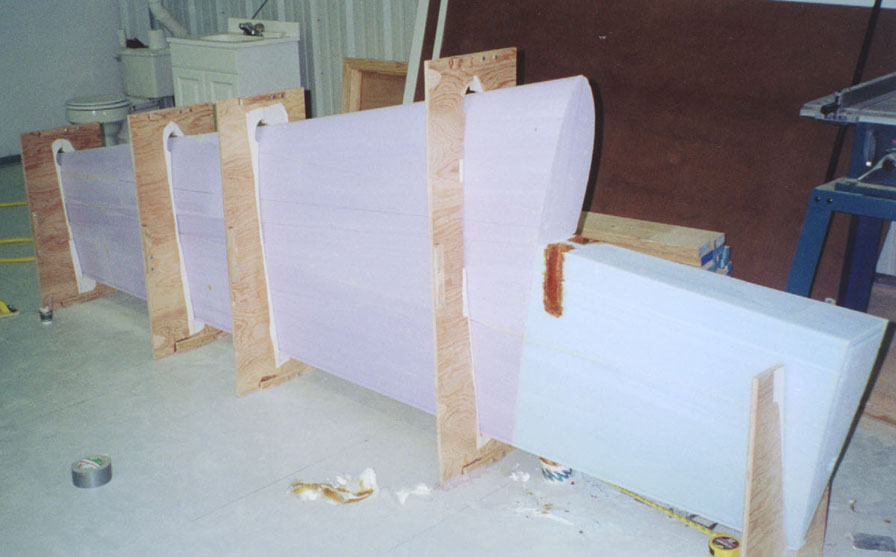
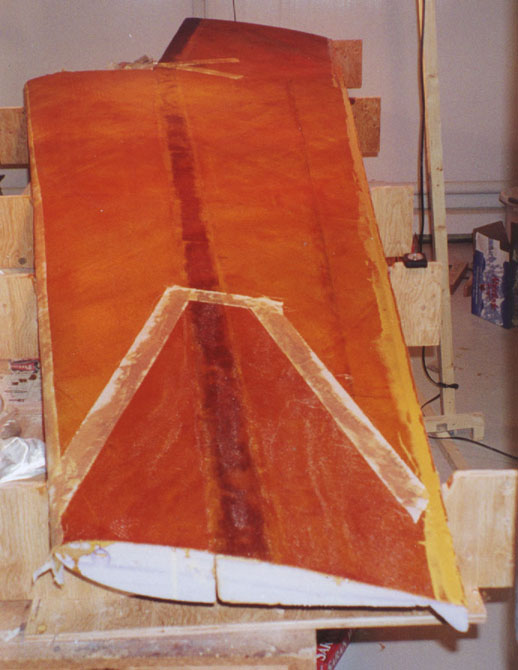
The right wing in the jigs, with the wing attach bolt fitting layups just knife-trimmed:
Shear web and spar cap I have no photos of.
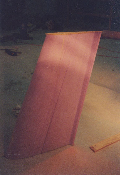
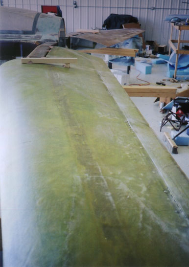
Finally, my brother and I skinned the bottom of the right wing.
Even at 60 degrees F in the hangar (IR lamps kept the work at 70-75), we
had to work fast!
After a lifetime of squeegeeing:
Whereupon a problem became evident: for the #5
jig, the jig is misaligned -- the trailing edge is 1/4" high! Hadn't
actually noticed it before, but I sure did now! Oops; had I re-read
some of Dave Orr's helpful hints and tips, I'd have known about it ahead
of time. Yes, the per-plans jigs are a bit off. Hey, I guess
that means I did it right....
Well, I'm certainly not going to have my inboard section that
far out of true...it'll create drag! So when it came time to put the
bottom jigs on and flip the wing so as to skin the top, first I cut down
the #5 jig at the TE. Then, I bondoed the whole thing to the table.
With luck, this'll hold the wing in the CORRECT position while the top skin
cures, locking everything into place....
It almost worked. What we did wrong was we bond'ed
jigs to the lower skin, and flipped the wing, after only 36 hours or so of
cure. It FELT fully cured, but the strong tension force pulled the
bottom skin away in a couple of 1" patches. It's repairable; just inject
a little micro and weight it down....but for the left wing, I'm waiting longer.
And I'm starting with the jigs in the correct orientation!
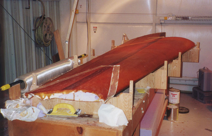
Notice, though, that the TE is die-straight and the wing looks
beautiful. Rapture!
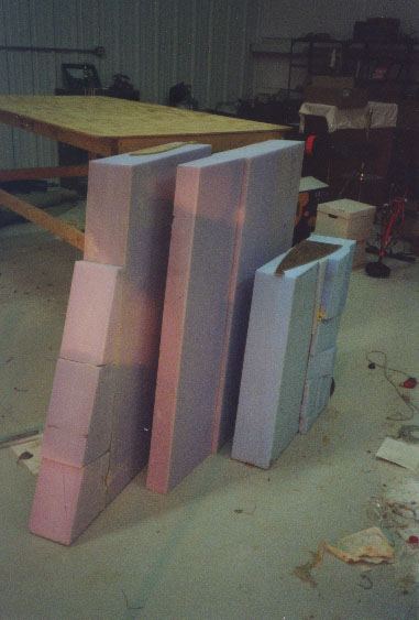
While waiting for things to cure, we amused ourselves by hot-wiring the left wing.
Most of the foam is old; came with the project.
But here I used some recently-purchased stuff from Aircraft Spruce.
At first I wasn't impressed; the stuff looked like it had been cut to length
with an axe! On further examination, though, I noticed that it was oversized
in every dimension. Hooray! This came in very handy; it completely
eliminated some of those "scrap foam piece" placements, and just cleaned
up the hot-wiring immensely.
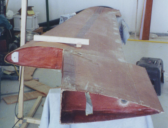
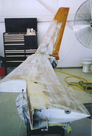
This is the right wing with aileron removed, the well glassed, and ribs glassed. Note the additional wing pin near the front edge of the wing; this it to prevent the leading edge from wiggling up and down during full aileron deflection. With the aileron lengthened 20", this pin is probably needed to keep the wing from flexing.
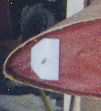
A close-up of the wing pin. It's an AN4-11A
bolt; the head is buried in the foam inside a 1/4" thick piece of aluminum;
the D-shaped piece you see here goes over the rib layup and is 1/8" thick.
Later, it receives a 1-ply BID cover (NOT shown here). Much later, I
plan to grind it to length and to a rounded tip; it will mate to a socket
on the outboard side of the strake.
An industrial accident claimed the photos of left
wing construction. (Lesson: if you're the sort of person who's
dim enough to snap away with a 35mm camera with no film in it, you must NEVER
leave that camera unloaded, at any time. Alternatively, spring for
a digital camera like a normal person.)
Suffice it to say the left wing looks a whole lot like
the right one, except that it's considerably yellower. This is actually
due to a minor change in the formulation of Safe-T-Poxy which has recently
taken place. Temperature and humidity were much higher during left
wing layups than they were for the right. Both are still in the tolerable
range, so strength will not be affected.
With both wings built and ailerons installed, it
was time to mount them to the spar!
These days, the fashion is to mount the wings to the spar,
THEN mount the spar in the fuselage. I didn't know that; I was silly
and did things per plans. Fortunately, the spar went on straight and
level...more or less. At the time of writing, the right wingtip is
1" low, and 3/4" further away from the pitot tube. These numbers are
well within tolerance, but I'm going to see if I can bring them to zero before
mounting the wings permanently.
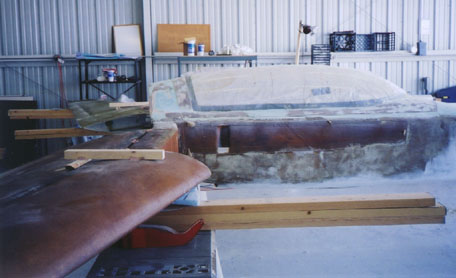
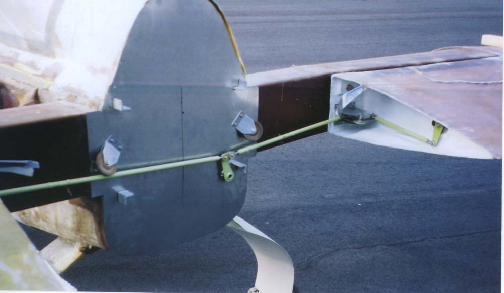
In the meantime, some photos of the wings mounted with Bondo:
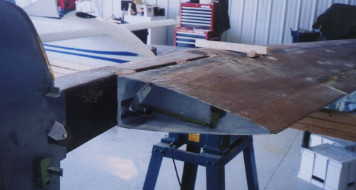
The wing supports are makeshift (sawhorses, lumber,
foam...in one case, a table saw). But they're sturdy, so they work.
During this process, I fiddled with the wings until they were exactly level and even in sweep and fore-aft, within the limits of my measuring ability. It took a lot of maneuvering, but I made the error mentioned above disappear. Measure thrice, cut once...it was time to drill holes for the wing attach fittings.
This was WORK! I opted to use the per-plans spot-face
tool, despite which the spot-face tool isn't really designed to drill a 5/8"
hole through that much aluminum and fiberglass. As a result, it got
HOT! Hot enough to delam the final layer of glass, in fact. Fortunately,
this was an inboard hole, so re-attachment was easy. After that, I
went MUCH slower, with frequent breaks to cool the tool. In fact, it
took me over a week to drill the holes. Eventually, they were done.
After a not-so-quick detour to Chapter 20 to attach the winglets,
I was ready to re-attach the wings!
This was MUCH easier said than done. Whoever billed this
as a "trailerable" airplane was stretching things; certainly it's not easy
for ME. Alignment went fairly well, but I overestimated the depth of
four of the six holes, and so had to wait for additional bolts. That
done, I found more problems. Many more.
The inboard attach bolts are almost easy. I can reach
both sides at once; I can see at least one side at a time. It only
took about two hours to get these down to a science.
The lower outboard attach bolts are harder, but workable.
I can see the front (nut) side through the lower hole in the spar, and reaching
both sides isn't TOO hard. About four hours, per bolt.
Alas, reaching the upper outboard bolts gets harder! Worse,
I found that on the right side I'd drilled my holes just slightly too close
to the top edge. What that meant was that, with the nut held in a socket
wrench, it won't quite align and allow itself to thread onto the bolt.
No, I have to hold the nut in place with a monkey wrench, turn the bolt until
it starts threading, THEN switch to the socket wrench, which works fine.
Guess how many times I dropped the nut out of the monkey wrench? And
of that million and one times, how many times do you suppose the nut fell
out the hole directly underneath it? Zero, of course...the nut always
went flying into the interior of the spar, and did NOT want to come out!
Murphy strikes again...and again.... I estimate about half a million
man-hours per bolt. With practice, I ought to be able to cut that time
almost in half!
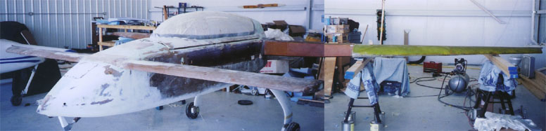
Happily, the wings are on. I plan to remove and re-attach them as few times as humanly possible:
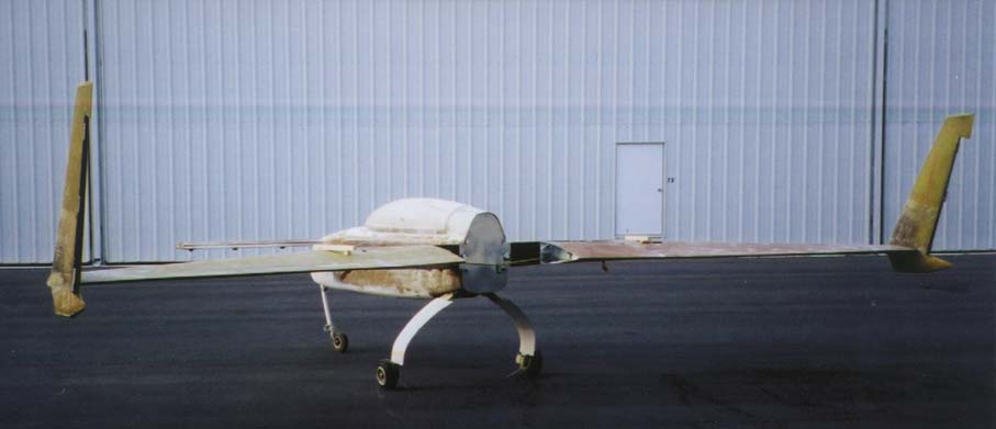
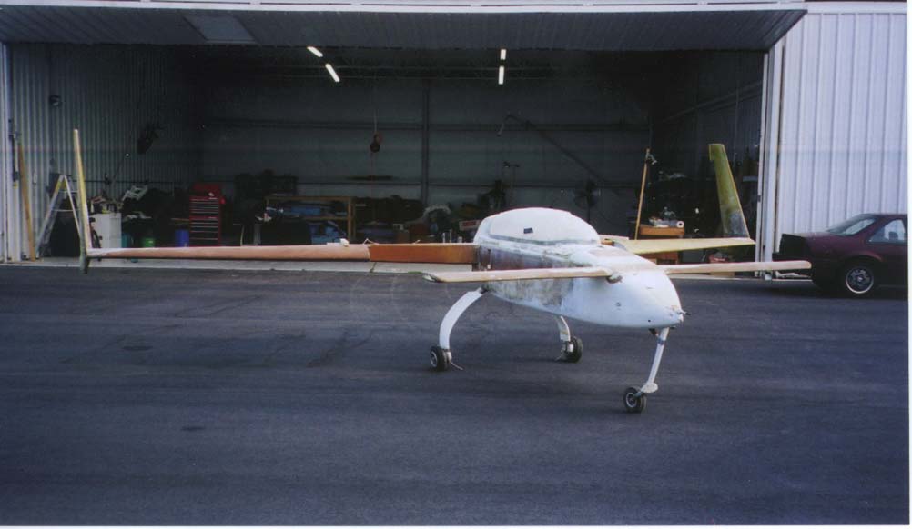
Very satisfying; it almost looks like an airplane!
At this stage, I also hooked up the aileron control rods
(Ch 17). The left side rubs on the rudder pulley, and will need some
adjustment of the bracket next time the wing is removed, but overall, it
works well.
Update 16 Jul 01: the wings are removed, the left side bracket HAS been adjusted to prevent rubbing, and the wings are getting sanded and filled. A long process!
Update 16 Oct 01: the wings get a multi-ply
carbon layup in the aileron well. Why would I do this? Well,
I was a bit concerned about the possibility of the upper wing skin flexing
in high-speed flight. Should aerodynamic forces move the upper skin,
with the attached aileron hinges, enough, the aileron could possibly contact
the lower skin. This could cause rubbing, or possibly even control
lock! It may already have caused an EZ accident. We can't have
that.
What to do? I'd already built the aileron wells
per plans except for the 20" aileron extension. I couldn't thicken
the skins appreciably, especially the hinges were already attached; it would
destroy the fairing line of the ailerons.
What I did was, first, I sanded off 1 ply layer at the
hinge attach points ONLY.
Then, I added carbon. I chose the carbon for its
strength and stiffness; a little bit would keep the skin from flexing. The
downsides: expense, the fact that carbon acts as a metal for purposes
of antenna reception (not really a factor; my antennae were far enough away)
and corrision (add a thin ply of fiberglass to keep from corroding the hinges!).
Also, the stiffening of the aileron well will also change the structural
characteristics of the wing, possibly undesirably. Since the aileron
well layups aren't integrated with the rest of the structure and don't run
to the wing root, I think the structural effects will be minimal.
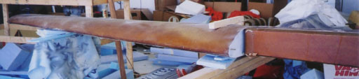
The new aileron well, before the final thin ply of fiberglass
on the hinge areas:
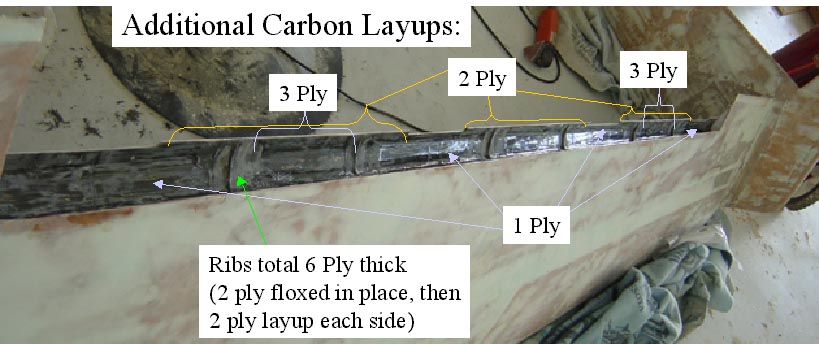
Net result: same thickness at the hinge attach
points, minimal added weight, and I can no longer move the top skin by squeezing
against the top and bottom, as I could when it was only glass.
I should have done this as an original build, replacing
some of the original layup schedule. Save weight and time. Well,
next time I'll know.
This "mod" should keep me safe during high-speed
flutter tests, Vne calculations, and other intentional violations of the
handbook's maximum speed.