The Whitcomb winglet design does something even more interesting: they PULL inboard, quite hard. This creates a vortex which tends to counteract the vortex created by the aircraft wing. The result is the wing "appears" to have a higher aspect ratio than it actually does. Result: more range, less drag.
Also, they're a handy vertical surface to build your comm antennas into. Even better, they look cool, which is, after all, the reason we fly.
After the experience with the wings, winglets seem
easy -- no jigs! Just hotwire the cores, add a urethane end cap (upper
winglets only), sand some nice rounded tips, and it's time to skin!
I also added a comm antenna on each. I also
hot-wired a little tiny wiring channel from top to bottom of each upper
winglet. CCI has
just started making a snazzy set of nav lights for the winglet wingtips,
and putting it there means less drag (= looking still more cool).
I can't resist.
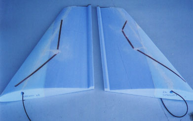
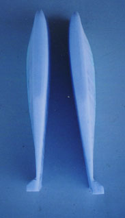
The results of my efforts after the above:
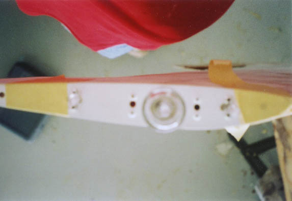
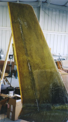
Note the markings for the big rudders.
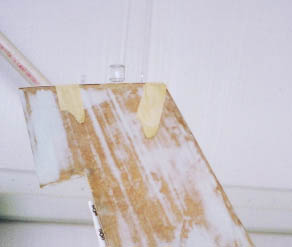
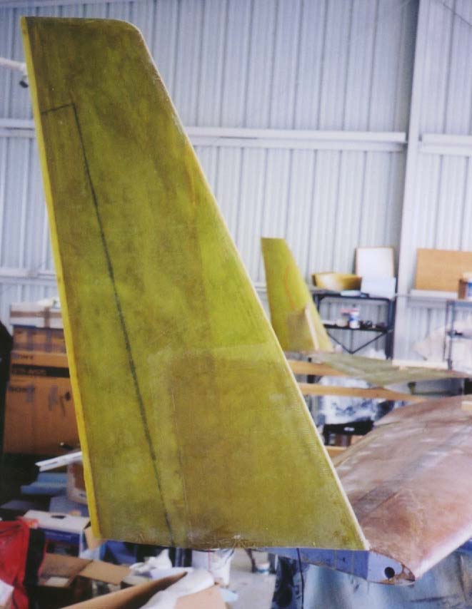
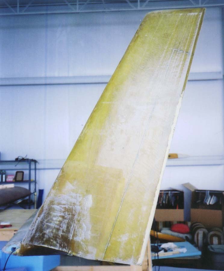
The lower winglets are simpler, though the camber switches direction between root and tip. Takes getting used to:
Laying up the winglet skins is a simple matter by now. Unfortunately, camera operation is not; I lost an entire roll of film at this point. (I need a digital camera!)
I tried the "Poor Man's Vacuum Bagging Technique". I figured it certainly couldn't hurt, and would only help; AFTER I'd squeegeed the layup to within an inch of its life, I put the plastic over it, and pushed out the air bubbles to let air pressure push the plastic down. When cured, the net effect is that the bumps and valley of the skin are more even, as the bumps are lower. Which should mean less filler, and less weight. A little.
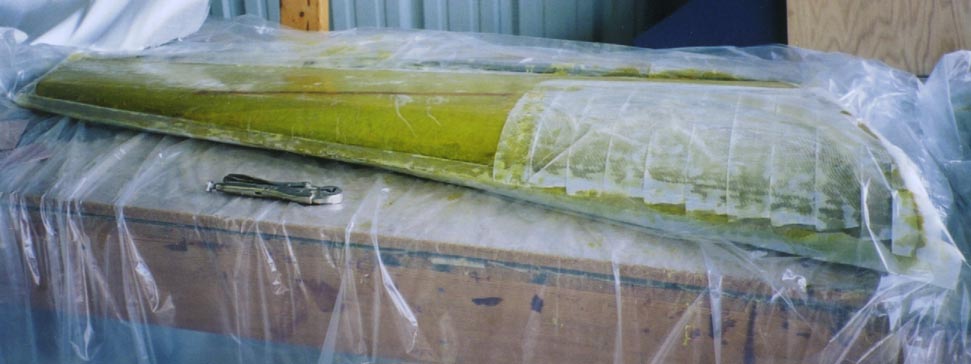
Right winglet in its final layup:
I deviated from the plans order a little to put the winglets on the wings while I had the wings carefully braced and leveled for drilling wing attach bolts. This way, I knew all references would be level and even. Besides, it took FOREVER to drill those wing attach bolt holes, and I needed something to do while waiting for the spot face tool and fittings to cool, so....
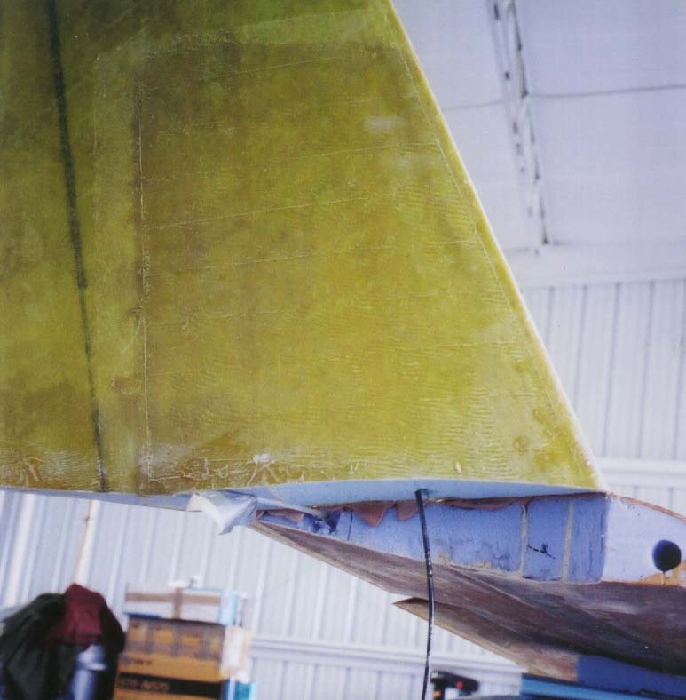
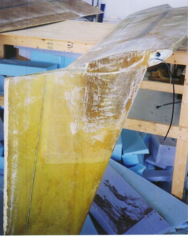
Here is a photo of the winglets bondo'd in place for alignment:. The cut foam interior of the joint:
I don't have any photos of the next few steps, where the inner corner
and rib layups are done. I also buried that comm antenna cable in
the foam, then buried some shielded 3-conductor for the winglet tip lights.
Then, the big strength layup, inside corner and outside:
The lower winglet was glassed in place (photo to follow),
then it was time to cut out the rudders.
Then, I got to hollow out a vast part of the interior
for the internal rudder levers.
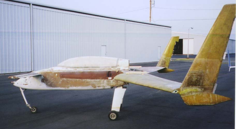
The airplane with wings and winglets (but not rudders)
mounted:
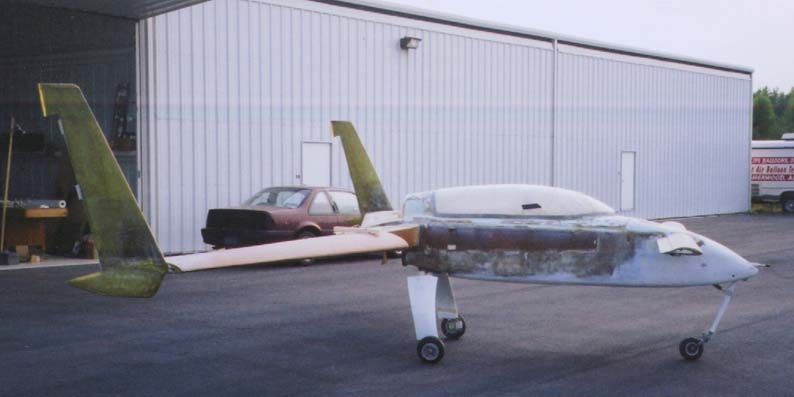
Eventually, I got the rudders on. Rapture!
The rudder has flush bellhorns. I'm using a system called "Internal
Rudder Levers" which is superficially similar to the Melville internal
bellhorn setup. It looks great and works well so far.
Update. Since the above was done, three major things have happened:
1. I've filled and sanded. A lot, a
lot, a lot.
2. While walking the flightline at Oshkosh,
I discovered the joys of countersinks. I came back and converted
all my aileron and rudder screws to flush countersunk for less drag and
a cleaner appearance.
3. I hacked off the winglet tips for installation
of the CCI tip lights. Here are some interim photos of the installation: