The Long-EZ strakes are "kinked" solely so that the inboard section would have the same angle as the Vari-Eze. (In the Vari, the strakes are much smaller, and hold only fuel).
Early on, I decided to eliminate this design backward-compatibility. By building the strakes with a single, straight leading edge, I would increase volume within the strake, for effectively no drag. Of course, this also moves the center of pressure forward very slightly, but if I also move fuel slightly forward, it will compensate. Which is exactly what I will do. This mod is hardly unprecedented; the "Big-EZ" N3R was built this way. So is each and every Cozy and Aerocanard. It works.
The strakes are one of the hardest parts of the airplane to get exactly right. The leading edges are notoriously difficult to get straight, and waves and dimples in the top surface are easy to notice, too. Switching to Cozy-sized strakes opened a new possibility; I could order strake skins from Aerocanard. This would save construction time and ensure a better-looking strake all at the same time.
The strakes arrived in a BIG box; I hauled them out
and got a good look. No instructions, but since what I'm doing is
nonstandard anyway, what did I expect?
The skins have an outstanding exterior finish, a
smooth interior finish, and appear to be laid up with EZ-Poxy. The
exterior will need refinishing and paint, though, after I've put BID tapes
to attach the edges, etc.
MY MISTAKE. Okay, so I sit down, think
about it a bit, measure a lot, and start cutting a strake. This is
nice, I say. The new Fein Sander, by the way, makes straight cuts
easy and fun. Too easy, perhaps, and too fun, because it turns out
I'm cutting in the wrong place!
What I did was, I cut off about 8" off the OUTBOARD
end of the strake. This was a mistake, because that meant the new
outboard end no longer matched the curve of the wing! (I was also
mistakenly cutting up a top skin instead of a bottom skin, but never mind).
Yikes! Cut mostly complete, I discover my mistake, and panic.
What to do?
THE CURE. I did what any self-respecting
composite builder would do: I glued the pieces back together...and
the faster the better! Then I sanded down the plies in the area of
the joint. And then covered that area back up with two plies BID.
In other words, I repaired the area per stock Rutan techniques. Whew!
Problem solved. Cost: 3 or 4 ounces and ten years' worth of
worry lines. But once painted, it should be about undetectable...In
the words of a Cozy builder, "No one will ever know".
Ya gotta love working with fiberglass, though.
Try fixing an aluminum part that way!

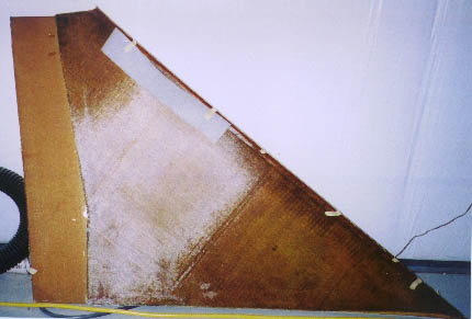
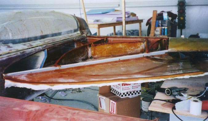
Okay, enough fooling around. I cut the INBOARD ends of the strake skins, and sand the final 1/4" or so to butt them against the fuselage, and micro in place:
Here I run into another problem. The foam sandwich doesn't reach all the way back to the spar; it ends a bit short of it. This is, again, because I'm trying to adapt a Cozy strake to a Long-EZ; it's certainly no fault of Aerocanard's strake skins. An easy fix, too; I just lay a bit of blue foam in there:
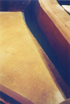
And glass (2 ply BID) in place, lapping onto the spar.
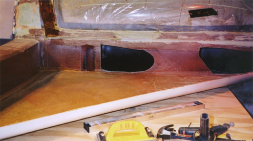
And now the hard part: I have to CUT HOLES
IN THE FUSELAGE! This is not easy; this beautiful bathtub, thus flawless
canoe, needs some big holes chopped in it! It takes me a while to
work myself up to this act of madness. Of course, I'll use the Fein
sander, not an axe, but still....
I measure twice, cut once, and still decide to make
the holes undersize on top so as to allow me to sand to a perfect fit.
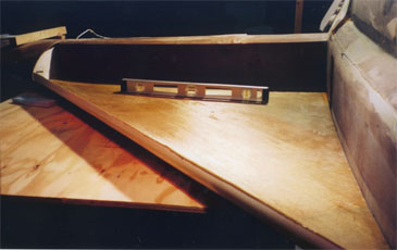
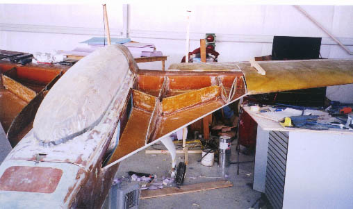
Now there's another problem; with the strake attached firmly at root and spar, it still wants to curl a bit too vigorously at the tip. You can sorta see what I mean in this photo, where only the barbell weight is holding it straight:
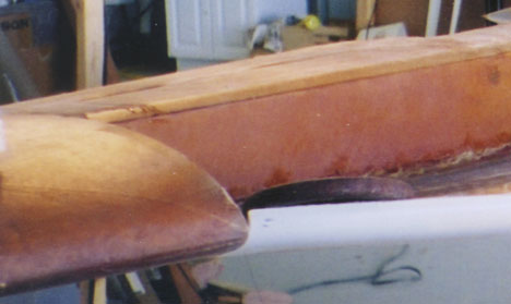
Nice joint, but I'm sure I'll have to remove that
barbell weight before I fly. Or even attach the top strake.
What to do? Then I realize I have ALREADY provided the answer when
I added the wing attach pin in the Wings chapter (Ch 19). With that
1/4" bolt sticking out from the wing inboard front to attach to the strake,
I can put that rib in first thing, holding the rest of the strake skin
in place. By the time the wing gets removed again, the strakes will
be a completed structure, with ribs and top skin holding the strakes in
their proper shape. Hooray!
I make a pair of ribs, drill and attach. With
some effort, everything aligns!
Okay, time to build the ribs. Here, due to the straight-edge shape of the strake skin, I've made a few modifications:
- There is no urethane cap
at the leading edge. Hence, no front-edge baffles. Fuel tanks
are wet all the way to the leading edge; baggage area is empty all the
way forward, too. Careful sealing at the leading edge will be called
for.
- Aft end of the baggage
area is unmodified, as is the butt line (BL23) of the outboard baffle.
Because of the longer distance to the leading edge, B23 is 7.5" longer.
- To trap slightly more
usable fuel volume at the same CG, I moved the leading edge of B45 outboard
by 5". It's now diagonal, starting at BL45 at the spar but moving
out to BL49 at the leading edge. B45 is actually smaller than per
plans.
- This necessitated extending
the diagonal baffle (DB) by 3".
- I didn't like the way
stresses at the leading edge were transmitted to the spar end of B45, so
I retained the outer diagonal (OD) to take some of the load.
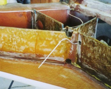
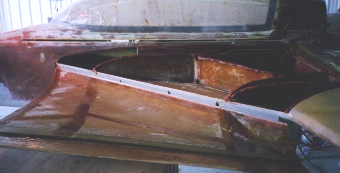
The result you see here:

I installed the tank vents (the plans vent line, plus an additional one running along the front face of the spar, teed into the same vent line). Then wire-brushed the tops of the fuel baffles and filled them with micro, so that a pinhole leak wouldn't destroy the foam. I also installed a pair of capacitance fuel probes from Wayne Lanza at Composite Design. These required some tube bending and drilling a new vent hole at the very top. It was a LOT easier to do this with the strake tops off than it would have been as a retrofit!
Enough procrastinating. Now it's time...to attack the upper skin!
This is a big step, because one false step here can lead to months of aggravation. Flox is troweled on the tops of the baffles, and the upper strake skin lowered into place. Too much flox makes the plane heavier, but too little means a leak in the fuel tank that can be very very hard to find and fix. Any twisting or jiggling of the upper strake skin as it's put in place can also move flox out of the way and cause a gap in the joint.
I attacked this problem in two ways. The first,
I call the "Flox Roll-up". In essence, I make a very small tube of
1 ply BID, wet, to hold some flox. This stays on top of the baffles
much better than a simple glop of flox. It also allows a slightly
wetter flox, and is thus less likely to leak. This is because only
very dry flow will stay on top of those baffles. Of course, those
roll-ups had flox troweled all around them...I wouldn't want the only joint
to be a narrow tangential one with 1 ply BID! No, we need every baffle
to join solidly with the upper skin.
The other way I attacked this problem was simply
that the pre-fab nature of the Aerocad strake skins helped me in several
ways. Since I could ensure both skins' leading edges matched up,
I had better control of position than the per-plans setup with its curved
foam block which is covered on one side and doesn't go all the way to the
leading edge. In fact...looking at the problem further, I realized
that by joining the two skins at the leading edge with duct tape, I could
make a "hinge" and prevent all unwanted movement.
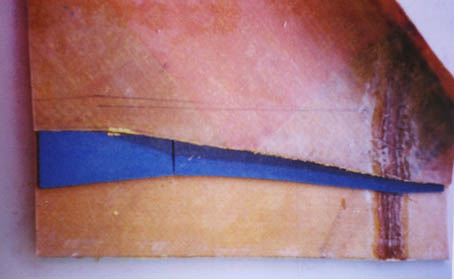
So I joined the skins this way, pulled the top skin
off, did my business with the flox, and put the top skin back on with the
"hinge". No muss, no fuss! What the plans say requires 3 or
4 people now requires 2 at the most, and with less likelihood for error.
But this trick only works, of course, if you take the kink out of your
strake; leaving it in makes this stunt impossible.
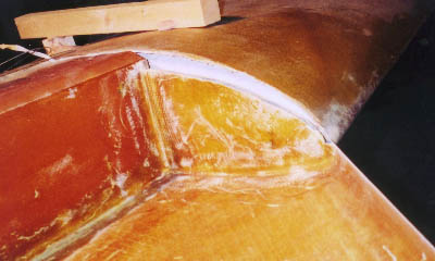
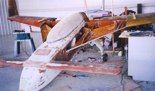
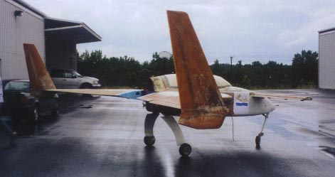
And, voila!

A 2-ply joint at the fuselage and a 2-ply leading edge, plus interior joints, complete the structural assembly of the tank and strakes. Whew! I just hope I didn't miss any major leaks in the fuel tank....
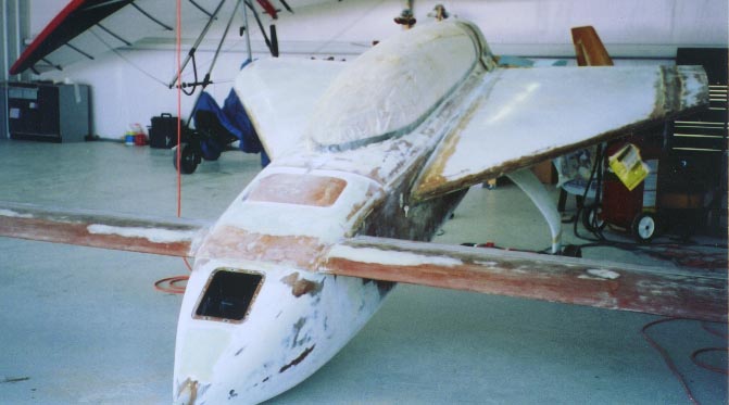
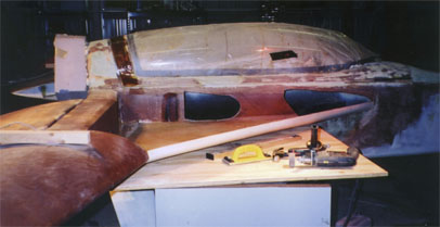
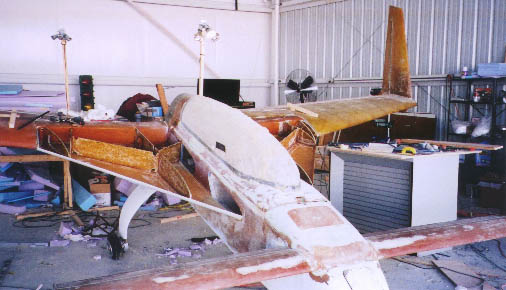
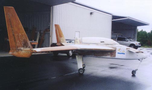
It looks like an airplane, doesn't it?

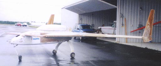
Blue foam inboard of the wings (inboard of BL 23)
are marking guides to aid engine accessory and cowl placement by marking
the inboard edges of the wing. With the wings off, I should still
be able to emplace foam and lay-up a cowling, eventually.
Leak checks took forever and a week, but eventually
came to an end. Once the obvious leaks are found, check your fittings
again...and again...and again, because they move, and that was always the
source of my leak. Well, except for the pinhole leak that was at
the inside of the upper fuse-strake joint, where it can't be seen.
Took me weeks to try brushing that spot. Oh, and try using a manometer
setup...I broke an altimeter through overpressure. Expensive mistake.
Update Jan 2002 -- More buffoonery!
More buffoonery, indeed When I mounted the
engine mount extrusions, I measured twice and cut once. Really, I
did. Looks like I should have measured thrice. At least.
Because the right lower extrusion came out 3/16" too high. No way
to fix it without removing and re-mounting that extrusion.
Okay, don't panic. You put them in once before;
you can do it again. What's the big deal?
The big deal is that NOW the holes are drilled in
the spar and longeron, so the new extrusion location will have to use those
holes. Okay, so we need a new extrusion; I have some. Let's
get started....
Oops. The bolts that run through the lower
longeron were floxed in place against just this eventuality. Unfortunately,
they weren't floxed well enough; they just turned when I tried to remove
them. So I was going to have to grind out the flox so I could get
at the nut, and remove the bolt.
Oh, now you see the problem. Because this
happened AFTER I leak-checked the strake, plainly, the sump blister is
on! How do I get to the nut, which is buried under the sump blister??!?
Surprisingly easily, once I mustered the courage
to do it. I simply ground holes in the sump blister (the aft one
was right at the aft corner), and again in the fuselage. I dug out
the flox, removed the bolts, pounded out the longeron (it came out depressingly
easily), checked the PROPER location of the new longeron, built a wet six-ply
layup to support it, and, when it was dry, drilled through the existing
holes into the aluminum extrusion. Then REALLY flox the bolts, vacuum
the inside of the sump out very very well, and repair the sump blister
per Rutan techniques.
At the outset, this project would have been beyond
me. But now it's easier to do than it was to say! I must be
learning something.
Here's the heartbreaking sight: I had to cut a HOLE in a perfectly good sump blister!
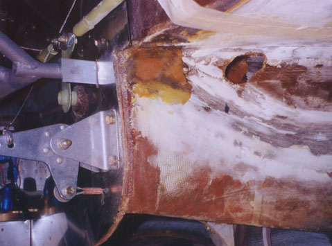
This shows the repair after I've put the new extrusion
in. The aft hole is already filled with flox, though it later got
a sanding and a BID overcoat. Inside the forward hole, you can see
I've floxed the nut. That hole in the sump is about to get sanded
layer by layer, and patched.
Which, in an amazingly short time, I did.
Whew. Breathe easier, everything is okay now....
But all things considered, it would've been nice if I'd test-fitted the engine mount against ALL extrusion hardware much earlier in this process.
Well. If we learn by doing, we learn twice as much by doing it twice. Or something like that.
If you're putting your extrusions in, fasten the
fuselage side with nutplates, rather than nuts. You'll be glad you
did, should you ever need to service this area.
Fuel Caps
The fuel caps went on before painting, in defiance of the manual's advice. I wanted something that seals better than the stock Brock caps, so I blew some bucks on a set of racing caps from ACS. They have a machined aluminum ring they fit into; the caps themselves are fiber and thermoplastic. I attached the cap with a chain, which also has an extension which stays submerged in the fuel, thus ensuring grounding at all times. I floxed the aluminum ring in place in the strake, used a bit of filler to smooth the top, and voila!
