Without a good engine, I might as well not have bothered working on the rest of this stuff. But reciprocating engines intimidate me! I never worked on my car as a kid; computerized fuel injection and dealer service plans were the norm by the time I could do that. Nor have I flown recips, much; all my Air Force time has been in turbines of one sort or another. I like turbines; light, reliable, everything spinning in the same direction, a soothing whistle to let you know everything is working right.
Not so, with a Lycoming. "Bits of metal thumping foolishly back-and-forth," as Robert Heinlein described it.
Well, tough. I wasn't building a glider, and I wasn't going to develop a turbine installation for EZ's. Not yet, anyway. So I was just going to have to suck it up, get my hands dirty, and deal with pistons and carburetors and crankshafts. Oh my.
I read Tony Bingelis' fine books on the subject -- twice -- then the Sacramento Sky Ranch book, as well as whatever Lycoming information I could get my hands on. And more.
Early on, I wanted an O-290. It's a very inexpensive engine, and its weight is probably better matched to the EZ than any other. I'd have to chuck the Dynafocal mount I'd inherited and buy a conical, but that wouldn't matter much.
In the end, though, I decided in favor of the O-320D. Bigger, better, higher, faster; I'm building an experimental airplane, and speed is not something I want to compromise on. Besides, it's a lot easier sharing tips and hints with the vast crowd of O-320 users than with the smaller group of O-290 flyers.
So I was staying with the Brock Dynafocal mount.
Unfortunately, that was designed for an O-235. Weldtech made an O-320
mount, but they're long since out of business, so I had to work with the
Brock O-235 mount. It was going to need some strengthening.
Some have used the O-235 mount as is with an O-320.
Some have developed cracks, some haven't. Since I plan to "G" up
the aircraft now and then, I won't take the chance.
Some have modified the mount with additional tubular
steel, bypassing the area around the upper cups. This certainly works,
but seemed a bit elaborate just to reinforce the top cups to keep them
from cracking. Moreover, I wasn't comfortable putting those tubes
on; I couldn't be sure I wasn't going to block accessories.
I went a third route. The mount was modified
with additional 3/16" steel plate gussets to allow stress to bypass the
joints around the upper cups. This should do the trick with a minimum
of impact. I painted it with white enamel, though, so any cracks
will show up easily.
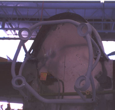

 This photo shows the gussets clearly; they fair the joints with the cups
in the top of the photo.
This photo shows the gussets clearly; they fair the joints with the cups
in the top of the photo.
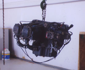
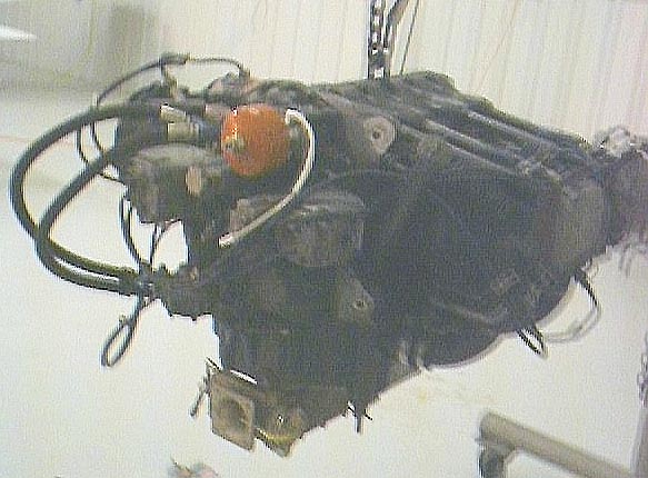
Okay, mount done; time to buy. After a couple of false starts, I found a fine engine at Broken Aero in Minnesota. O-320D2B, 700 hours SMOH, accessories, good condition. I inspected it, found nothing obviously wrong with it, and handed over the check.
A D2B means a 160HP model. I can't run it on MoGas. The "B" means instead of slick magnetos, it has retard breaker mags and a "shower of sparks" ignition system. Good thing I went with the small gussets for the mount; full stress-bypassing tubes would have blocked the oversized mags!
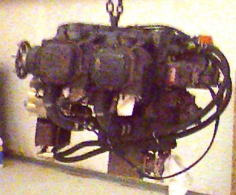
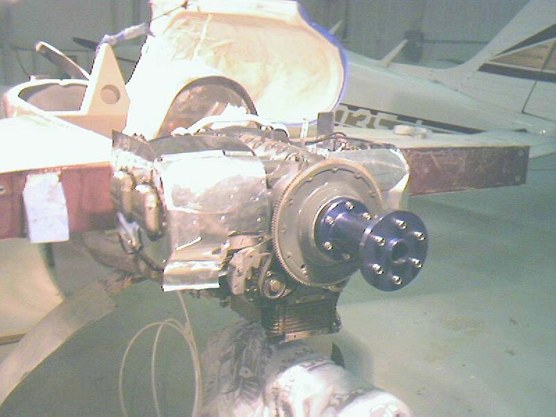
I hauled it into my hangar after dark, so no pictures. The next day, I took a couple:
Once accessories begain arriving, I went to work. Off came the Marvel Schleber carb, the vacuum pump (bleah!), the Prestolite starter (thunk!). On went, respectively, the Ellison TBI, the B&C SD-8 standby alternator, and the B&C starter. The alternator, oil, and fuel pumps stayed where they were.
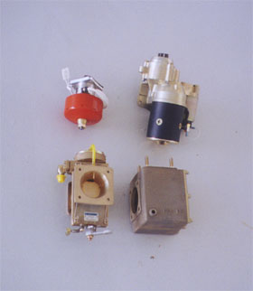 Just plug
N Play! Easier than I thought it would be, though there's still a
lot of work to do with the Ellison airbox.
Just plug
N Play! Easier than I thought it would be, though there's still a
lot of work to do with the Ellison airbox.
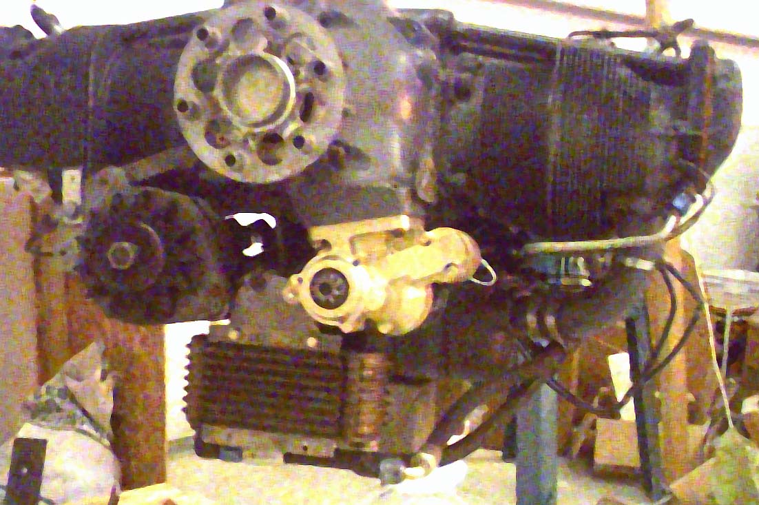
The oil cooler was mounted near the aft of the engine, where it'll have
its own NACA duct and an outlet at the aft of the boat-tail.
To mount the oil cooler, I had to cut and bend steel.
Not my favorite activity, but I'm getting better at it.
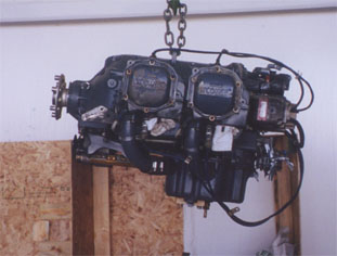
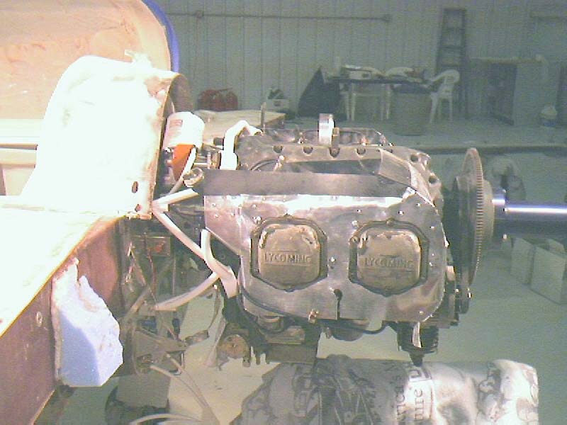
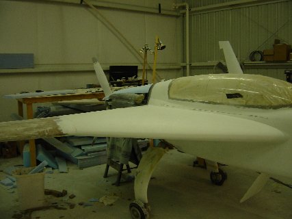
Herewith, the interim engine about ready to hang
on the mounts:
Subsequently, I mounted the (B&C) remote oil filter, and the Saber 8" prop extension. I started work on baffling for downdraft cooling, then mounted the engine so I could give the hoise back to its rightful owner.
March 3, 2002: the day the airplane gained 265 lbs.
Hooray!
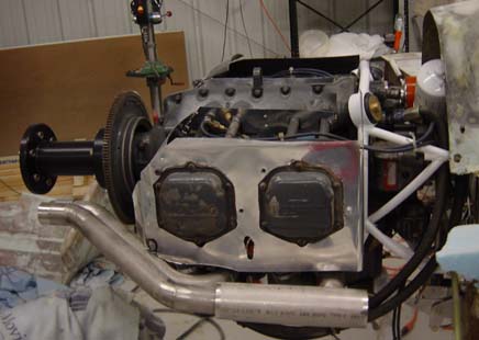
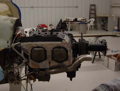
May 5, Hal Hunt exhausts are in, they look nice: 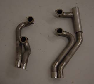
I trial-fit them on the engine. Some adjusting of the baffling is necessary:
I ordered the wrong size hole for my prop! I'd mismeasured, and asked for a size too small. Fortunately, Craig Catto was very understanding, and helpful, and with the order of a proper reamer, I was on my way again.
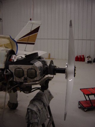
Aside from that, the prop installation went very smoothly:
With the prop in place, I discovered I wouldn't be using the second,
optional bulkhead for the spinner -- it wouldn't fit. I had already
made a paper-mache spinner, so as to make it easier to cut and align.
I made a temporary alignment tool out of pipe fittings: 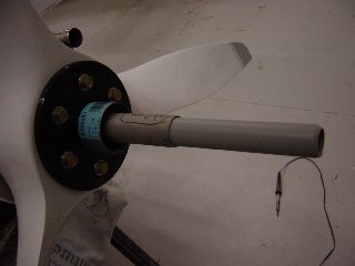
And slipped the false spinner into place: 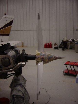
With that, I could cut the prop holes for the REAL spinner, and put
it on.
Finally, I could test the engine in good conscience. Here goes: 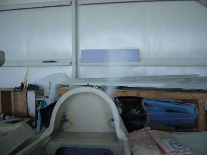
Hooray! I makes noise! And it moves a lot of air, too!
A bit of fiddling with fuel lines, oil pressure sensors, fuel pressure
sensors, and a fuel flowmeter, and it was time to downline the engine for
a while while I built the cowling.
I'd decided on downdraft cooling, which pretty much let out the stock
Aircraft Spruce cowl. No, I was going to have to build my own!
The cowl, I decided, would NOT be attached by screws. No, sirree,
those tend to go through the prop. No, for me, I would use hinge
material to hold the cowl on at the sides. I'd remove the pins to
pull the cowl off. The cowl would have lips that fit into slots at
the forward end to prevent movement there.
I ordered a length of Carbinge, and attached it to the engine sode
of the wings at BL23. I built the lips and slots at the forward edge
of the cowl. It looked like this: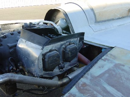
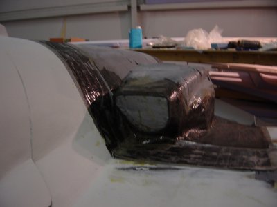
I covered the engine with foam, mostly urethane, and shaved and shaped it to suit. Then, covered the foam with duct tape. An eternity later, I had a form I could use; laid up stiffeners, carbon UNI strands, and 3-4 ply carbon BID over everything, and voila! A cowl!
Back in Black
As of this picture, the bottom cowl isn't done, but the top cowl is
built, and the hellhole is covered. All will require additional interior
ribs for stiffening.
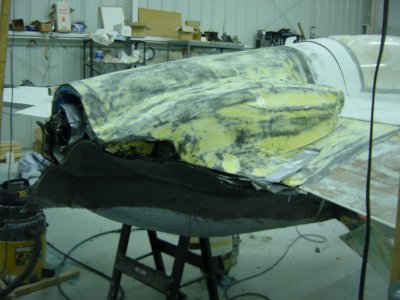
Now, both cowls are built and faired. Ribs are installed,
and rubber seals are in the lower cowl's oil cooler scoop. Pictures
to follow.