Basic Electrical Layout
Thunderduck has an all-electrical panel. Redundancy means two independant electrical systems. The Left (Essential) is the big one; the Right (Main) is a small bus, powered off an 8-amp alternator mounted on the vacuum pad. Each system has its own battery. In an emergency, the two systems can be joined, but rarely would this be a good idea. Both systems are 14V. The layout is almost identical to that described in the Aeroelectric Connection, Fig Z-14.
Since the nose is stock length, it's crowded in
there!
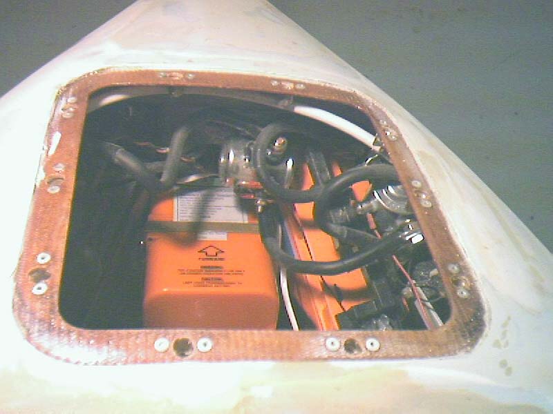
Here is inside the nose compartment. Visible
is the right side contactor and the crossfeed contactor, the right side battery,
and the ELT. The left side battery is black, and the left side contactor
in shadow, so you can't really see either.
The Panel
I wanted an all-electric panel. No vacuum gyros allowed! This meant two independent electrical systems; the second system is powered by a B&C alternator that sits on the vacuum pad.
I went through a phase where I wanted the main electrical system to be 28v and the backup to be 14v, but I got over it. All electrics on the airplane are 14v.
So the electrical system consists of a 14v battery
on either side of the nose. The left battery is hooked up to the essential
bus and the big alternator. The right-hand battery is connected to
the accessory bus and the SD-8 alternator. The only common point is
the firewall ground, but a switch allows joining of the two systems for use
in emergencies or for starting for better cranking.
The batteries are ordinary sealed RG units with 17Ah
capacity. At first I was going to use a pair from Powersonic, but I
figured a battery with a fast-on tab wasn't the smartest thing to trust your
electrical system and life to. So I ordered a battery, same form factor,
with bolt-on tabs from Newark. The right-hand bus, though, will stick
with the fast-ons, and we'll see how well it works.
The entire bus layout is pretty much identical to the two-bus layout described in Appendix Z of the AeroElectric Connection . Except that the second bus is powered by an SD-8, not a full-size alternator.
Per AeroElectric
Connection
philosophy, I'm running everything off fuse blocks.
As for the panel, I've been doing most of my panel using Panel Planner, like everyone else!
My panel had to meet some tough requirements. I want to fly cross-country AND acro for fun, I want to fly IFR when I need to. I'm a military pilot with many C-130 hours worldwide and fond memories of the T-38, so my panel should look a bit like that. I've grown so used to an HSI that I refuse to live without one on an airplane I'm building for fun. So, my panel had to:
- Be IFR-capable
- Have an HSI
- Have a moving map of some sort.
- Keep the attitude indicator and HSI on the centerline
of the airplane
- Be ergonomically laid out, with all controls logically
placed and ready to hand.
It's not easy to do; I tried!
Okay, so sitting down with Panel Planner 2.7, I
laid out my dream cockpit: 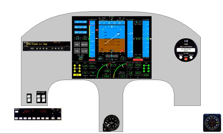
Right. So maybe the $20k Archangel glass cockpit is a bit much. And it doesn't even have a map display! What could I do on a realistic budget?

Now this I could do. The AV-10 engine monitor and the vertical card compass I'd already bought along the way. The gyros would be electric. The Rocky Mountain Instruments MicroEncoder would serve as the transponder encoder, as well as serving full-time as the airspeed indicator (it couldn't replace a 2.5" VVI). The transponder would be in the left armrest. The Sandel electronic HSI could be added later; early on, I'd use a DG-10 or similar. And that left the only high-dollar item being the one I HAD to have to make everything fit; a Garmin GNS-430. Expensive panel -- in fact, more expensive than the rest of the plane -- but if that's what it took to meet my requirements, I'd have to make it happen. I had my checkbook ready.
Then I went to Oshkosh, Airventure 2001.
While there, I learned a lot about what other EZ drivers were doing. I imitated them by picking up a set of Terra avionics. And, best of all, I discovered Blue Mountain Avionics . I'd heard of them before the show, but their talk of a vacuum-driven gyro for the glass panel I found very offputting. I wasn't impressed by the fact that it used a vacuum pump; I expected to be unimpressed by the rest of it.
Not so, I'm happy to say! Very much not so. For starters, there was an all-solid-state AHRS option (it's standard now). For another, the glass cockpit was very nice indeed...full instrumentation tapes, HSI display, AND moving map with sectional, enroute charts, etc...on DVD updates. And for a price I could afford! In fact, since the GPS receiver in the avionics obviated the need for the GNS-430, I could substitute a reasonably priced, small comm and nav (the Terra units). The price of the panel went DOWN...way down...while the functionality of it went up. I threw down my deposit the next day.
Here is my planned panel now:
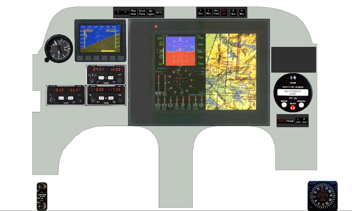
(Right-click and Show Picture to see it up closer).
This panel more accurately matches the contours of my actual instrument panel. It has room for everything, keeps the attitude indicator in the center, and is just about ideal. The transponder goes in the panel, which is a lot more realistic. I'll be stuffing the panel controller, intercom, and light dimmers in the armrest; enough is enough! Net result: much better panel, saved over $5k.
Note the standby ADI is shown as a Dynon all-in-one unit; I had it in my Panel Planner database. I'll probably go with the Blue Mountain Mini-EFIS instead; it's more expensive, but it'll probably be available sooner. It fits in the same space as the Dynon, but needs a big square hole, where the Dynon fits over a 3 1/8" hole. The main advantages of staying with Blue Mountain for the Mini-EFIS are a common supplier base, and common symbology! The Dynon uses display symbology conventions different enough from the Blue Mountain as to slow down a crosscheck and make accidents possible.
And, due to money and availability of these mini displays, I'll probably stick an electric gyro in there at first. This will be a later plan.
The thought of avoiding gyros entirely is very appealing; TWO battery-backed-up electric EFIS' on two different electrical systems provides better redundancy, anyway. (A nice counterpoint to the "No Mags" stickers you see now and then. Someday, I'll have three: "No Vacuum," "No Gyros," and eventually, after I retrofit dual electric ignitions, I'll have a "No Mags" sticker. We improve most where we eliminate old technologies, I guess. For fun, I can always request "No Gyro" vectors any time....)
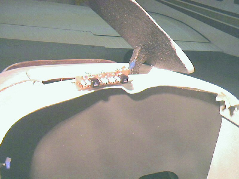
Illuminated Pushbutton Indicators?
Yes, this is one of my space-saving notions. The illuminated pushbuttons can go in the narrow strip along the top of the Blue Mountain Avionics display, where there isn't quite room for a true switch. The pushbuttons are push-on, push-off latching, with a light in the button. They're Switchcraft 67000 series, if you must know -- DC rated to 0.5 amps, so a couple of them (pitot heat, boost pump) will have to drive relays. The buttons are labeled with decals, painted black elsewhere, and covered with a clear coat. When pressed, you can see that it's in, and the light illuminates to tell you it's on. In the case of the alternators, they'll illuminate green when on, and red when the regulator detects a problem! All in all, a neat-looking way of saving space. If I can bring it off. Stay tuned for developments. Here are two of the buttons, illuminated, on the front deck of the airplane:
The Crotch Panel
This is my name for the area around the fuel valve. The fuel valve location is per plans, though I sprang for the Allen premium fuel valve. Rather than covering it with an aluminum panel, I used foam and fiberglass. Then I got busy, cramming as many little-used items in here as I could:
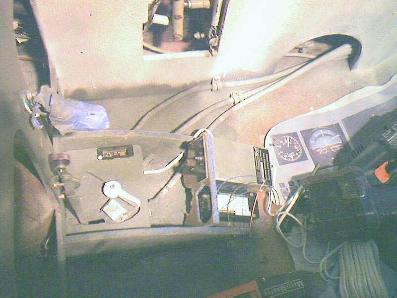
Here is the aft sub-panel being test-fitted. It will be placed flush with the aft edge of the fuel valve panel, and the front seat thigh support will cover most of this area. In addition to the fuel valve (with a metal tab to prevent inadvertent OFF), there's the stock landing light lever, the ELT remote, the CO2 detector, and the PS Engineering intercom. Okay, the intercom isn't exactly little-used, but I expect adjustment to be easy and intuitive. Volume won't need much adjustment, as it will be adjusted individually at the headsets. Squelch won't need too much playing, once it's set once, and the knob is in the center, easy to find without looking.
These sub-panels look so smooth because I'm trying something new; one ply of the Rutan BID (8.8 Oz/Sq Yd) with another ply of much lighter BID (1.45 Oz/Sq Yd). Now, I don't hold with the school of thought that says to cover your fuse with the thin stuff; this gets you a smooth finish, but a lot of epoxy (weight!) gets added in the weave voids. But for interior parts, as an alternative to two plies of the heavy stuff, it's considerably lighter and about as stiff.
You can also see my (Panel Planner) printout of the panel, TWO handy drills (you can never have enough drills), and, at the bottom of the picture, my trusty Fein Multimaster multi-tool. I love this tool; if I were a little more musically inclined, I would write a song about this tool. If you don't have a Fein, GET ONE. 'Nuff said.
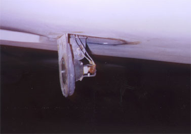
The Landing Light
As you can see in the above picture, the landing light extension lever is stock per the plans addendum, except for the fancy knurled anodized aluminum knob (thanks, Dale Martin!). But I couldn't bear the thought of putting in one of those enormous antiquated glass rice bowls masquerading as aircraft lamps. No, I went to the hardware store and picked up some 12V track-lighting lamps. The 75W narrow-beam is what I used; Home Depot has discontinued them, but you can still get them through Newark .
The smaller light went into a smaller bracket, made from the bottom skin of the fuselage. Vertical fiberglass stringers stiffened the panel, and a plastic lens cover was glued in place in the center. The light is held in place by a metal bracket made of a kitchen strainer (!) and aluminum sheet.
There's a microswitch buried in the fuselage floor; when the light is retracted, the light is off; when it's extended, it switches on. Simple.
Here's the light in action. This is well off the axis of the beam, but the reflector still glows pretty brightly, and the camera got saturated:
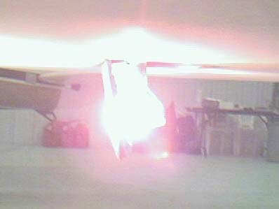
Like the plans setup, there's a big slash through
the lit area where the nose gear leg is. Oh, well; a light in the nose
wouldn't have this problem, but I didn't go that route.
Warning Horns
These are wired per plans, although a voice warning
via the AV-10 engine monitor will probably be added.
There are two microswitches in the throttle; one actuates
in the last 1" of low throttle travel by contacting the throttle lever against
the switch lever directly. The other is the high throttle switch associated
with the canopy alarm; the last 1/4" of travel pushes a rod through the
panel, actuating the microswitch. Okay, so not exactly per plans.
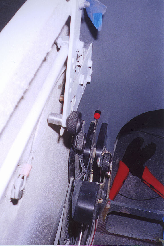
Here's a space-saving idea: the horn defeat
button is an illuminated (LED) pushbutton, so it's also the light.
It's also blocked by the throttle lever at high power settings, but since
you'll only press the button at low settings, this is no problem.
This shot shows the horn defeat button, the throttle
quadrant (no armrest yet), the modified throttle with speedbrake switch and
PTT button, the canopy release, the canopy microswitch, more anodized aluminum
knobs, and, on the far left, the key-driven external canopy release.
And the instrument door release, wrapped in blue masking tape at the very
top. And my ratcheting wire crimper. Oops; bad photo setup.
EFIS
In terms of sheer panel area, the EFIS is the biggest step! Mounting the box proved a challenge; I was expecting someplace to drill and tap screws for shock mounts. You don't get those; you get a plastic case with rubber footies. Hmm. Instead, I built an aluminum tray for it, fastened to the floor and the nose gear bulkhead. The box is clamped to the tray (I briefly considered bungees), with rubber at all the contact points to isolate it. The power supply is attached to the underside of the tray. A sheet aluminum creation fastens the DVD drive to the EFIS box.
But the biggest step was cutting that big hole
in the instrument panel! Once I'd done that, there was no going back.
Or correcting a mistake. Measure thrice, cut once. I took
a deep breath: 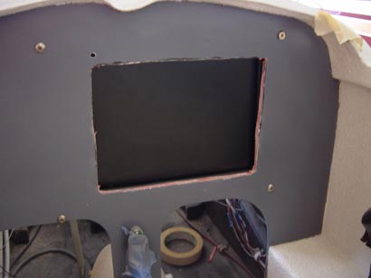
And the results, eventually, turned out okay.
Now would probably be a good time to mention that I
had to drill into the display immediately, and tap the attach screw holes
from the front. This way, the EFIS could be mounted to the back of
the panel, and viewed through the hole. If I mounted the EFIS on top
of the panel, as intended, not only would I cut down the structural strength
of the panel quite a bit (it'd be a bigger hole), but the landing gear crank
would bump into the display and scratch it up. Embarassing.
So I sanded, and test-fitted, and sanded, and test-fitted
some more, and painted a little to see what it looked like. This is
what it looked like:
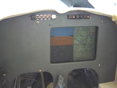
Yippee! Everything worked out more or less as planned!

As time went on, the panel got more complete:
The AV-10 engine monitor is also working. It's 74 degrees in the hangar. You can tell, because that's what the EGT sensors are reading. Also the CHT's, oil temp, and carb temp.
The Terra avionics stack is in, but not wired yet.
The pitot-static system, to include the standby altimeter, Blue Mountain Avionics set, and the 60-knot pressure switch (Hobbs meter) are plumbed.
The electrical system mostly works. Shown here are both battery buses powered, with the crossfeed connector closed. Right and Left magnetos are also engaged. Press the primer button and then the start, and it'll crank!